We use cookies to make your experience better. To comply with the new e-Privacy directive, we need to ask for your consent to set the cookies. -LEARN MORE ABOUT OUR COOKIES-
Virtual Channels using the nanodac Recorder / Controller
Using virtual channels to create calculations using maths and how to produce totalisers and counters
This application note will describe how virtual channels can be used to create calculations using maths capabilities and how to produce totalisers and counters and these will be illustrated using three application examples:
The first example uses the maths channels to produce two trend charts, one in °C and the other in °F.
Counters are used to count trigger inputs by wiring to any suitable internal or external source. The second example shows how to configure a counter to count how many times a channel goes into an alarm condition.
Totalisers allow the user to maintain a running total of any input channel, or any maths channel. Using maths channels, it is possible to totalise combinations of input channels so that, for example, the sum of two channels or the difference between them could be totalised. The third example shows how to configure a totaliser.
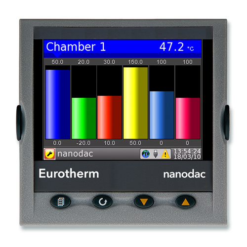
nanodac Data Recorder with PID Control
The nanodac recorder/controller provides combined recording and control in a single, compact ¼ DIN package.
Eurotherm has taken its extensive knowledge of secure recording and accurate PID control and combined them in one small box with a display that is so strikingly clear it belies its size.
The nanodac recorder/controller offers the ultimate in graphical recording combined with PID control for a box of its size. The compact ¼ DIN panel mount unit offers four high accuracy universal inputs for data recording and PID control. This secure data recording device with accurate control is enhanced by a full colour, ¼ VGA display to bring a crystal clear operator interface to even the smallest of machines.
Applications with up to Four Real Universal Inputs
The nanodac recorder/controller is ideal for use on any application requiring up to four real universal inputs. An additional fourteen inputs can also be written to over communications effectively making an eighteen channel data logger. Two PID control loops can be added for applications such as ovens, furnaces, chambers, etc., where it is required to monitor temperatures and control the loads.
The nanodac instrument can perform the following maths functions:
Add - Input 1 + Input 2
Subtract - Input 1 – Input 2
Divide - Input 1 ÷ Input 2
Multiply - Input 1 x Input 2
Group average - instantaneous sum of all points in the group divided by the number of points in the group
Group minimum - instantaneous value of whichever point has the lowest value
Group maximum - instantaneous value of whichever point has the highest value
Modbus input - the value written to the channel’s modbus input
Copy - allows an input or other derived channel to be copied
Group minimum latch - the lowest value reached by any point in the group since the last reset
Group maximum latch - the highest value reached by any point in the group since the last reset
Channel min - the lowest value reached by input 1 since the last reset
Channel max - the highest value reached by input 1 since the last reset
Channel average - the average value of input 1 over a specified time
Display Measured Data in °C
This example works through the steps necessary to display measured data in °C on Channel 1 and the same data in °F on virtual channel 2.
Configure Channel.1.Main to measure temperature and configure ‘Units’ to ‘°C’.
To carry out the calculation °F = (°C*9/5) + 32 two virtual channels are used. Virtual Channel 1 does the multiplication 9/5 (1.8) and Virtual Channel 2 adds 32.
Select Virtual Channel 1 and set parameters as follows:-
Type - Math
Operation - Multiply
Input 1 - wire to Channel 1 Main PV
Input 2 - 1.8 (9/5)
Select Virtual channel 2 and set parameters as follows:-
Type - Math
Operation - Add
Input1 wire to ’ Virtual Channel 1 Main PV
Input2 - 32.00
Virtual Channel 2 is used to display the Trend chart as well as the recorded (archived) data.
Wire Virtual Channel.1.Main.Input1 to Channel 1 Main Input

Counter Channel 1 Alarm 1
This example creates a Counter which increments each time Channel 1 Alarm 1 becomes active. A counter is used to count trigger inputs up to a maximum of 1,000,000.
Counters can be cascaded by wiring from ‘Rollover’ of one counter to ‘Trigger’ of the next.
Steps to be configured:-
1. Configure a Virtual Channel as a Counter.
A typical configuration is shown:-
In this example each time the ‘Trigger’ input changes from No to Yes ‘PV’ increments by the value set in Input 1

A practical counter requires ‘Trigger’ to be wired to a source such as a digital input or, as in the case of the example below, to an alarm output.
1. Configure Channel 1 Alarm 1, for example, absolute high.
2. Configure a virtual channel, for example, Virtual Channel 3 as a counter and enable the counter (‘Operation’ =‘On’).
3. Wire ‘Channel1.Alarm1.Active’ to ‘VirtualChannel3.‘Trigger’
Each time Channel 1 Alarm 1 is active the counter will increment by the value set in ‘VirtualChannel3.Input1’. (This would normally be 1).
To Reset the counter using Digital Input 1
1. Configure a Digital Input, for example ‘DIO_1A1B’ for ‘Contact Input’
2. Wire ‘DIO_1A1B.PV’ to ‘VirtualChannel3.‘Preset’
Each time Digital Input is true the counter is reset to the value set in ‘VirtualChannel3.‘Preset Value. (This would normally be 0).

This example creates a Totaliser.
Totalisers allow the user to maintain a running total of any input channel, or of any maths channel. Using maths channels, it is possible to totalise combinations of input channels so that, for example, the sum of two channels or the difference between them could be totalised if required.
The maximum capacity for each totaliser is 1,000,000. This range can be expanded by wiring from the ‘Rollover’ output of the totaliser to the ‘trigger’ input of a counter.

The totaliser equation is:
tott = tott-1 + [(mat/(PSF x USF) ] where,
tott = totaliser value this sample
tott-1 = totaliser value last sample
mat = process value this sample
PSF = Period Scaling Factor (Period)
USF = Units Scaling Factor (Units scaler)
Note: the time between samples is 125ms.
Steps to be configured:-
1. Configure a Virtual Channel as a Totaliser.
A typical configuration is shown:-
In this example, every 10 seconds the totaliser will increment by the value of input 1.
In a practical Totaliser Input 1 would be wired to source such as a digital input or an internal source such as an alarm output in the same way as the Counter example 2.

